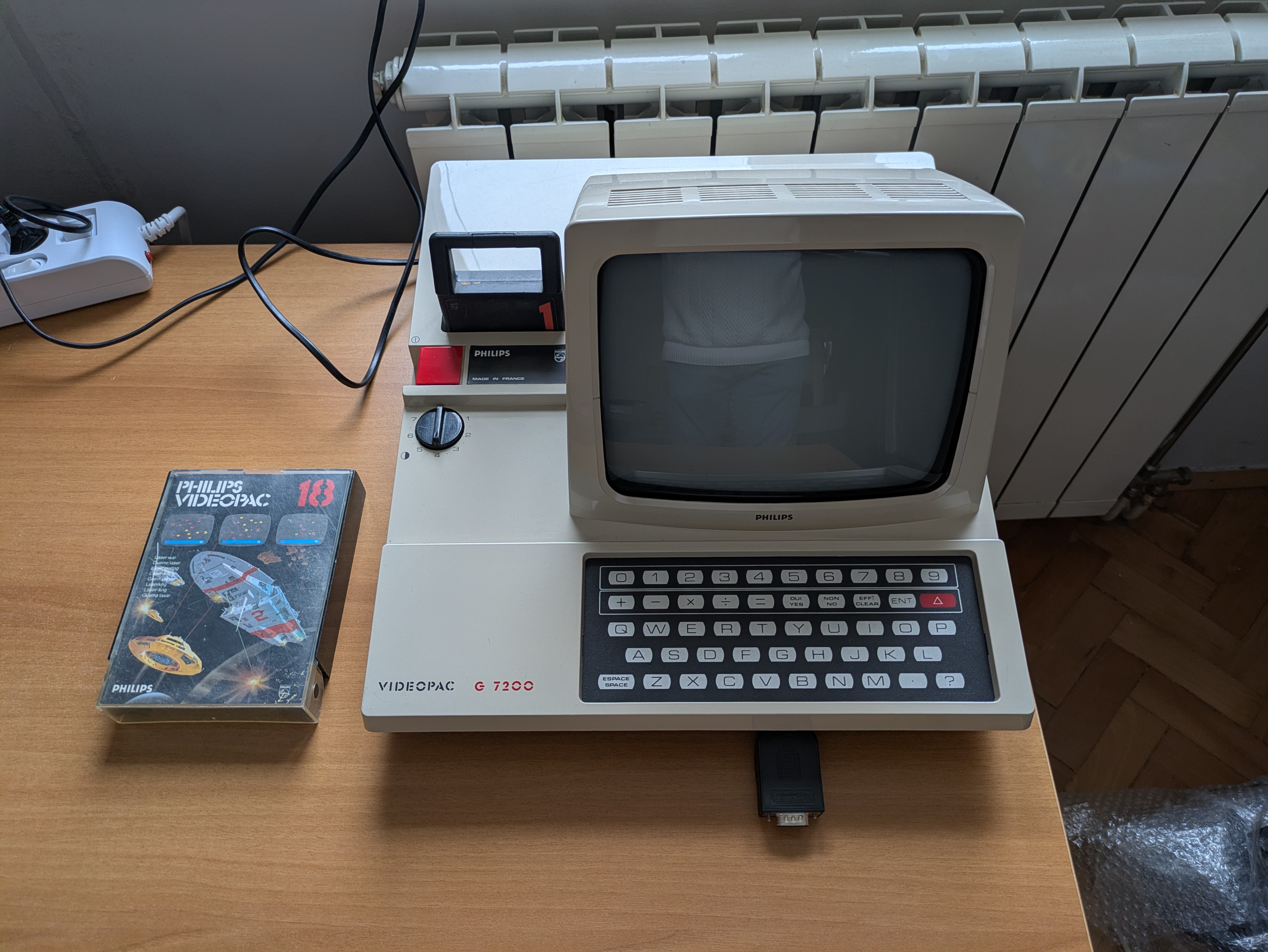
The Philips G7200 is one of the stranger relics of early home gaming: a Videopac/Odyssey2 console with a built-in 9" black-and-white CRT monitor. It’s a charming hybrid—part game console, part mini arcade cabinet—and it’s also tricky to repair due to the combination of digital logic, analog video circuitry, and switch-mode power supply (SMPS).
I found one on eBay in excellent cosmetic condition. Internally, however, it was anything but healthy.
1. First Inspection: A Dead Console With a Broken Switch
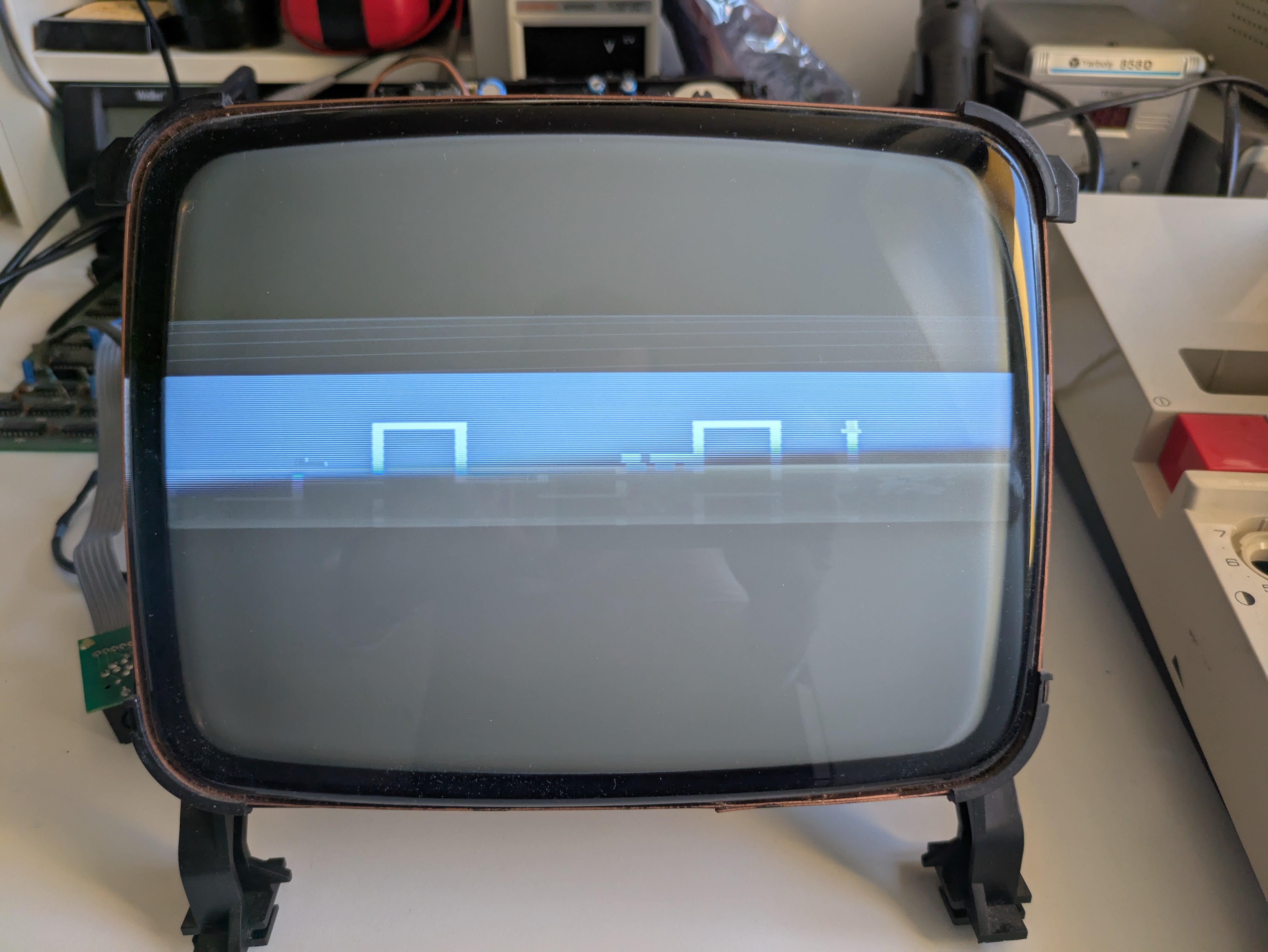
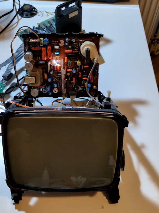
When I received the unit, it simply wouldn’t power on. A quick inspection of the mainboard revealed a simple starting point: the power switch was broken. I temporarily bridged the switch to see if the system would do anything. To my surprise… it did. A picture appeared on the CRT.
But the image was incredibly narrow horizontally, only about 30% of the expected width—likely a problem in the horizontal deflection circuitry. Still, this meant the CRT worked, the tube had emission, and the core console wasn’t completely dead.
2. A Costly Mistake: The Spark Incident
Then I made a classic beginner’s mistake—on a machine that absolutely punishes it.
While reflowing what looked like cold solder joints near the large primary capacitors C196 and C197, I forgot that the device was powered on.\ When the soldering iron touched the joint, a huge spark jumped between the iron and the capacitor.
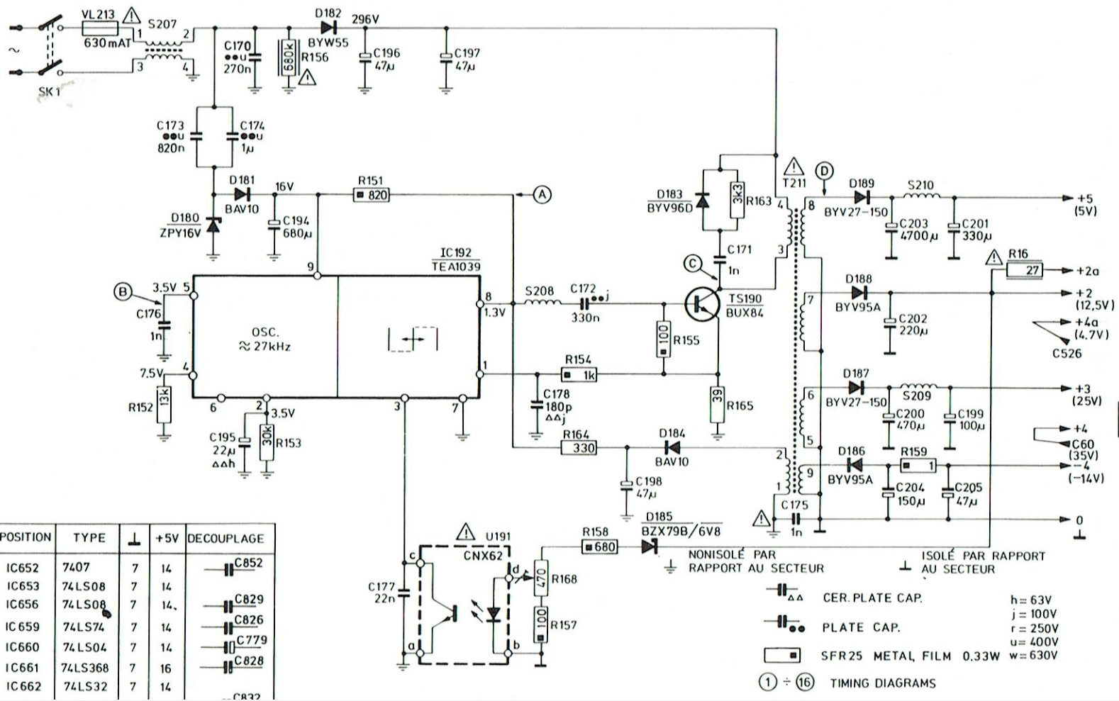
Despite the shock, the capacitors still measured within spec. But from that moment on, the fuse (VL213, 630 mA) blew instantly on every startup. Something in the high-voltage section had clearly died. The high voltage section is shown here:
3. Diagnosing the Power Supply: A Trail of Dead Semiconductors
The spark had clearly pushed a surge through the primary side. I tested everything in that area.
Findings:
- D182 (BYW55) — blown in two pieces. Definitely dead.
- TS190 (BUX84 transistor) — shorted.
- D180 (ZPY16V zener) — tested OK.
- D181 (BAV10) — tested OK.
- D183 (BYV96D) — tested OK.
- IC192 (TEA1039) — no shorts detected.
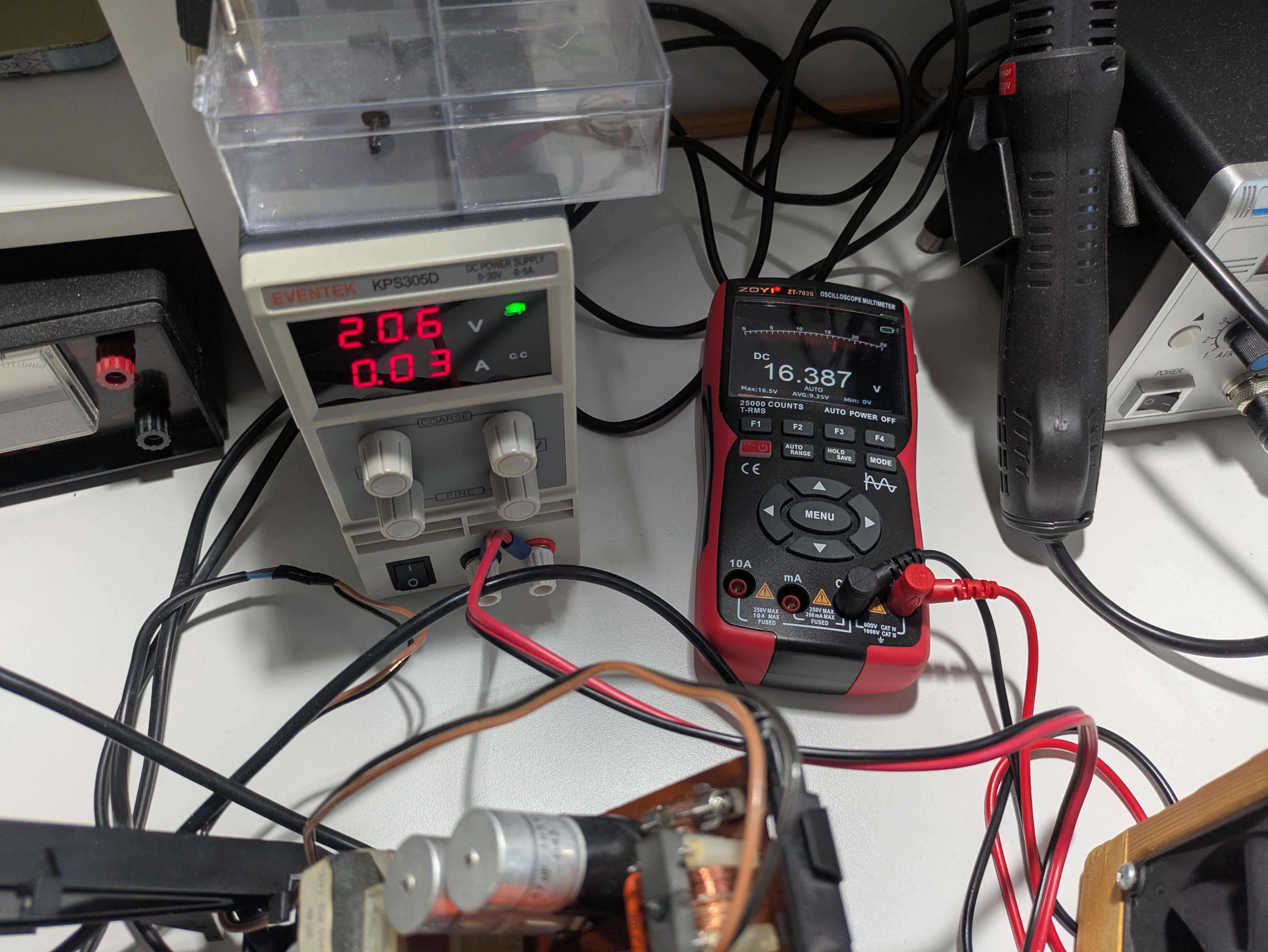
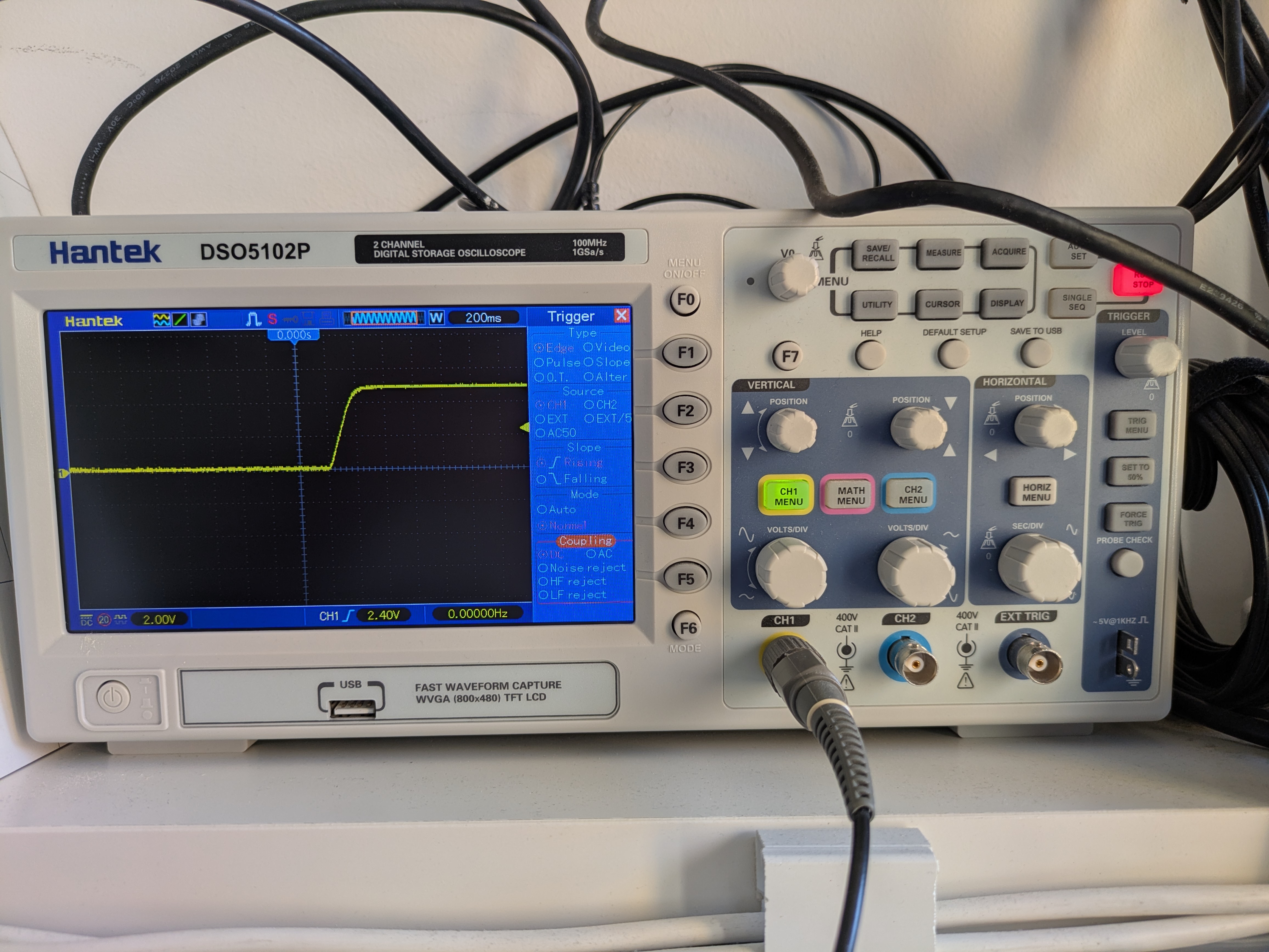
In order to test the zener diode D180 I did a proper test by checking the reverse voltage with the following setup:
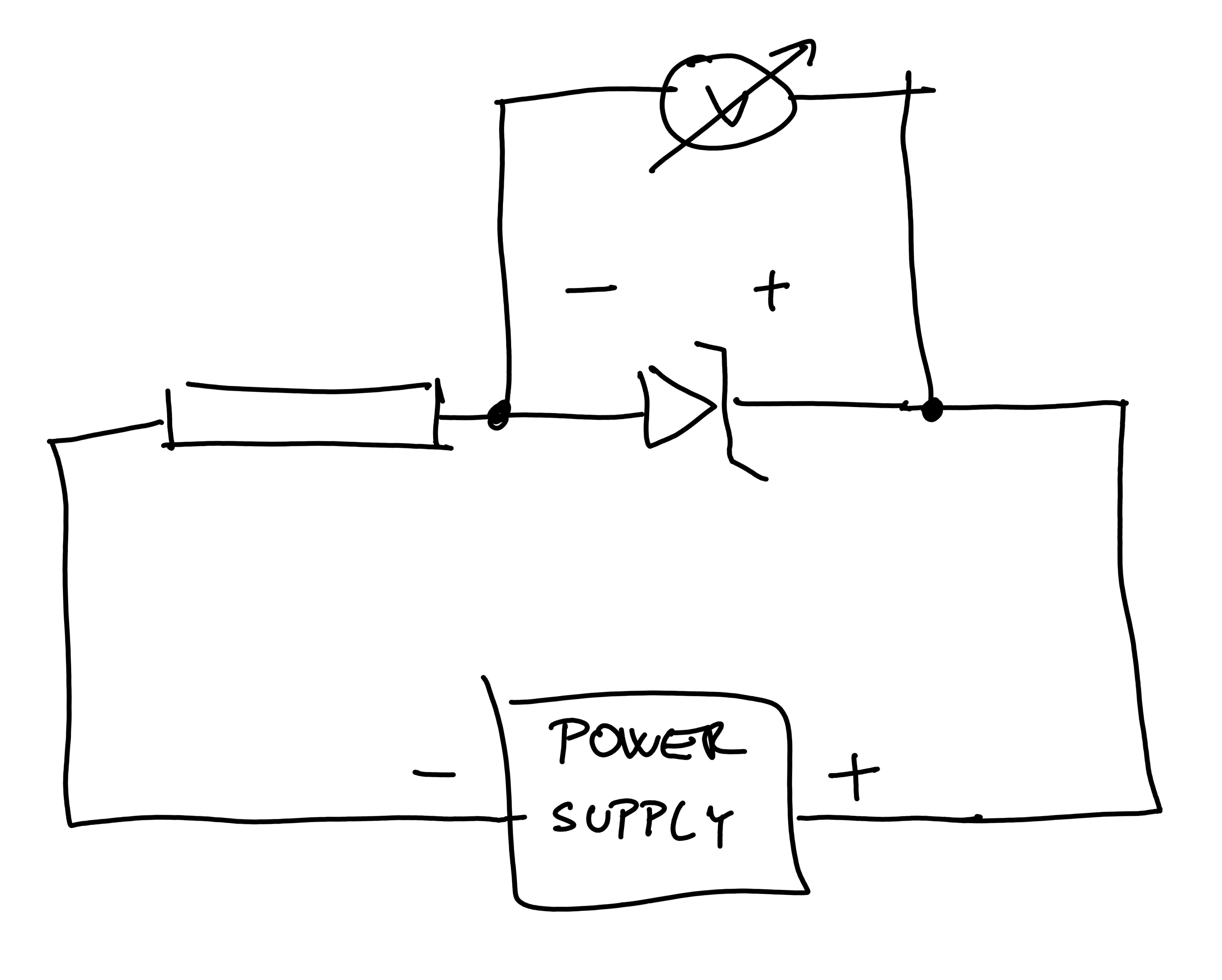
Difference between power supply voltage and voltage drop on the diode. Also, see the small current running through the resistor.
Conclusion:
The BUX84 transistor was the major casualty. But it was out of stock everywhere—so I ordered a BUX85, a pin-compatible replacement.
4. Replacing the BUX84… and Accidentally Shorting It Again
I installed the BUX85 and powered the unit on. Immediately, a bit of smoke appeared near the transistor area.
After investigation, I found the issue was not the transistor. Too much thermal paste had bridged the mica insulator and caused a short between the transistor and the heatsink, blowing the fuse again.
After cleaning and reinstalling everything, the G7200 powered up successfully.
5. Fixing the CRT Image: Vertical Deflection Failure
Once the power supply was stable, I turned my attention to the vertically narrow image. A similar repair documented here was helpful:
https://www.tsb.space/bl0g/videopac-g7200-display-not-good-and-no-audio/
From the service manual:
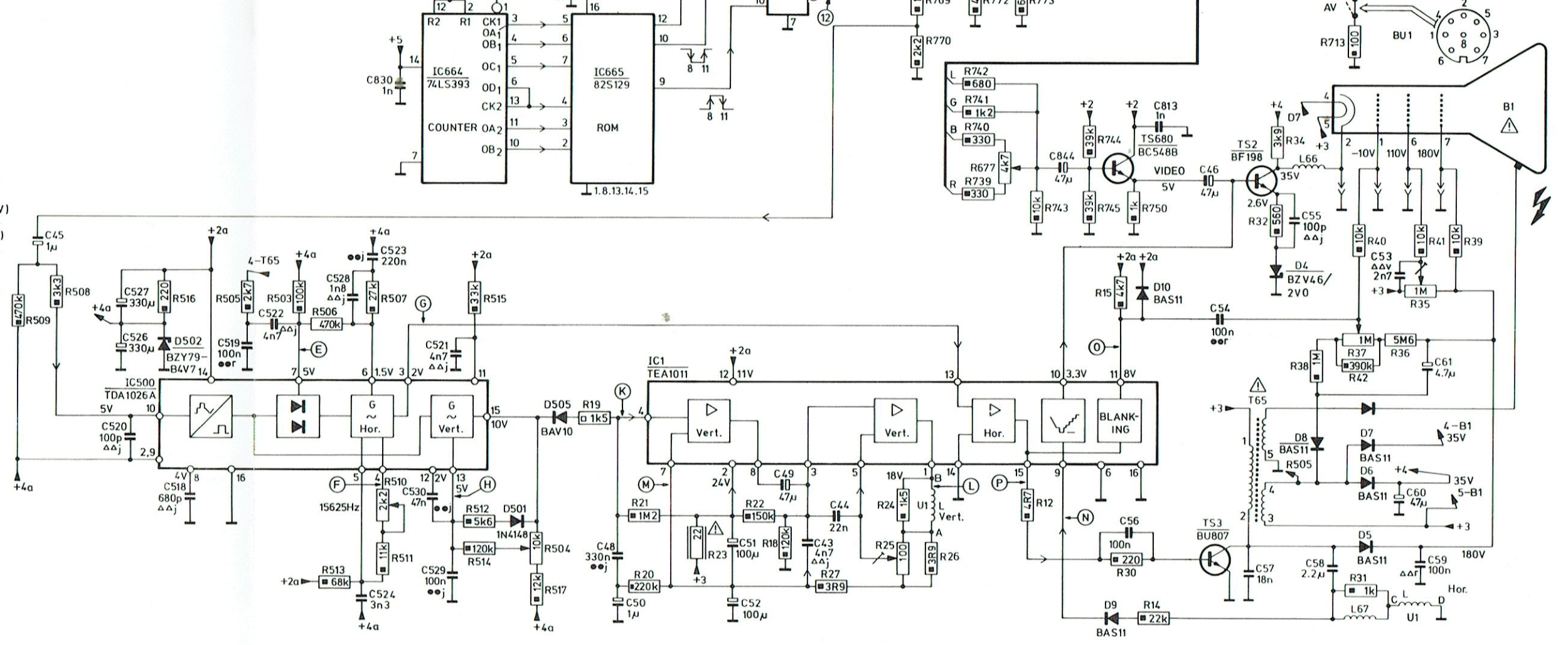
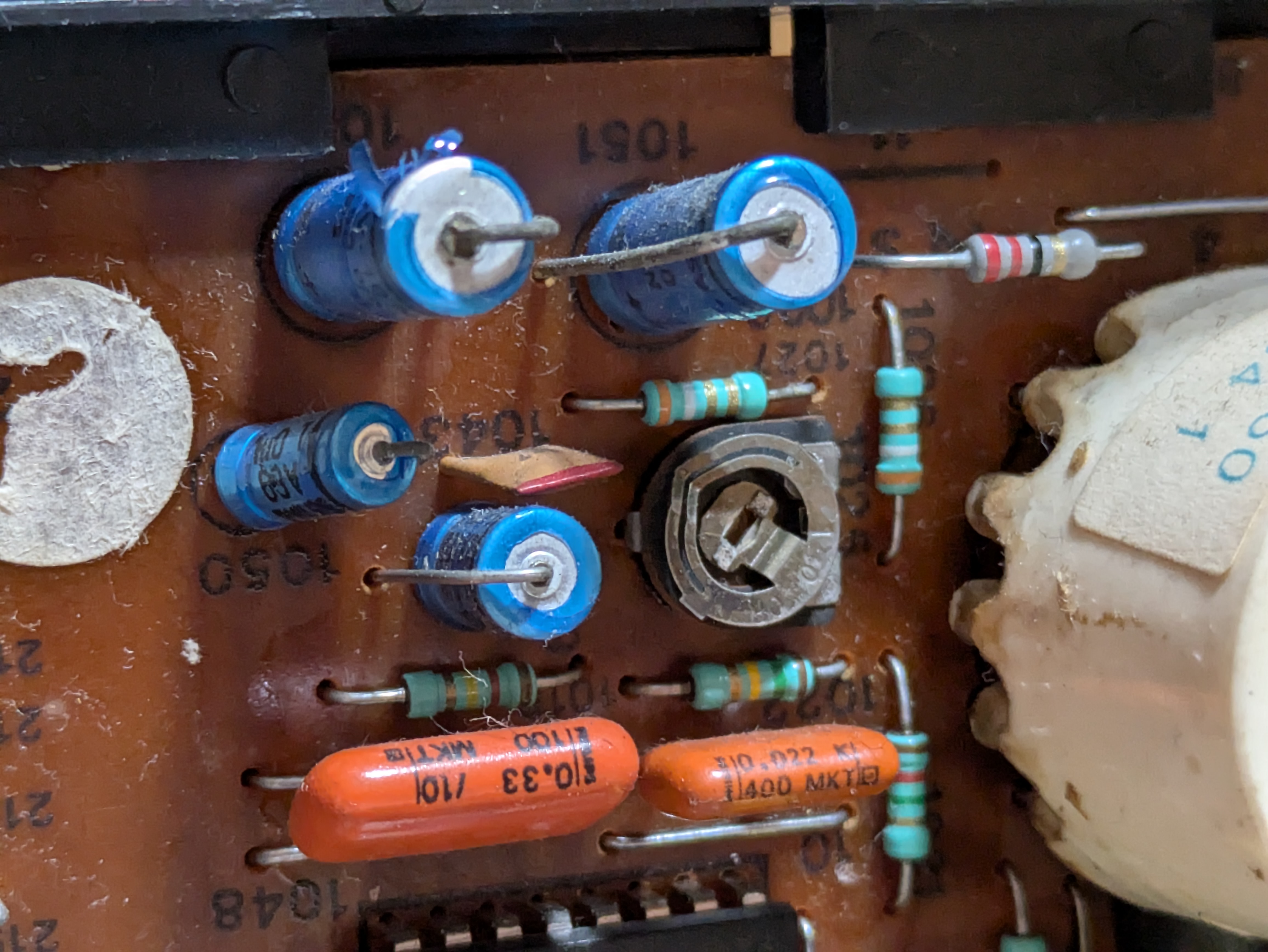
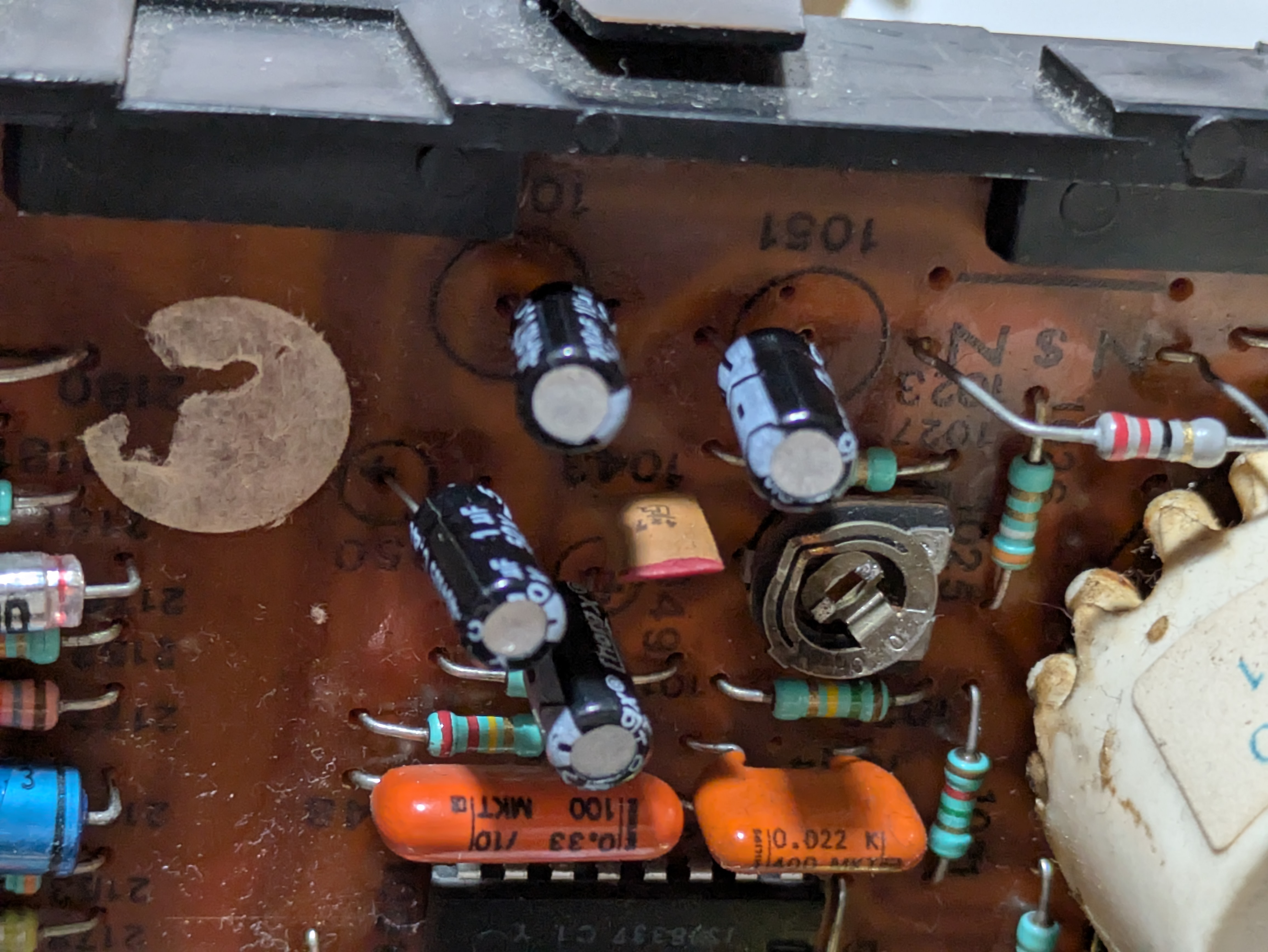
I removed and measured the capacitors around IC1 (TEA1011):
- C49 (47µF)
- C51 (100µF)
- C52 (100µF)
- C50 (1µF)
Actual measurements: 100µF, 70µF, 47µF, 1.6µF. They were not really that far from the specs but I replaced all of them.
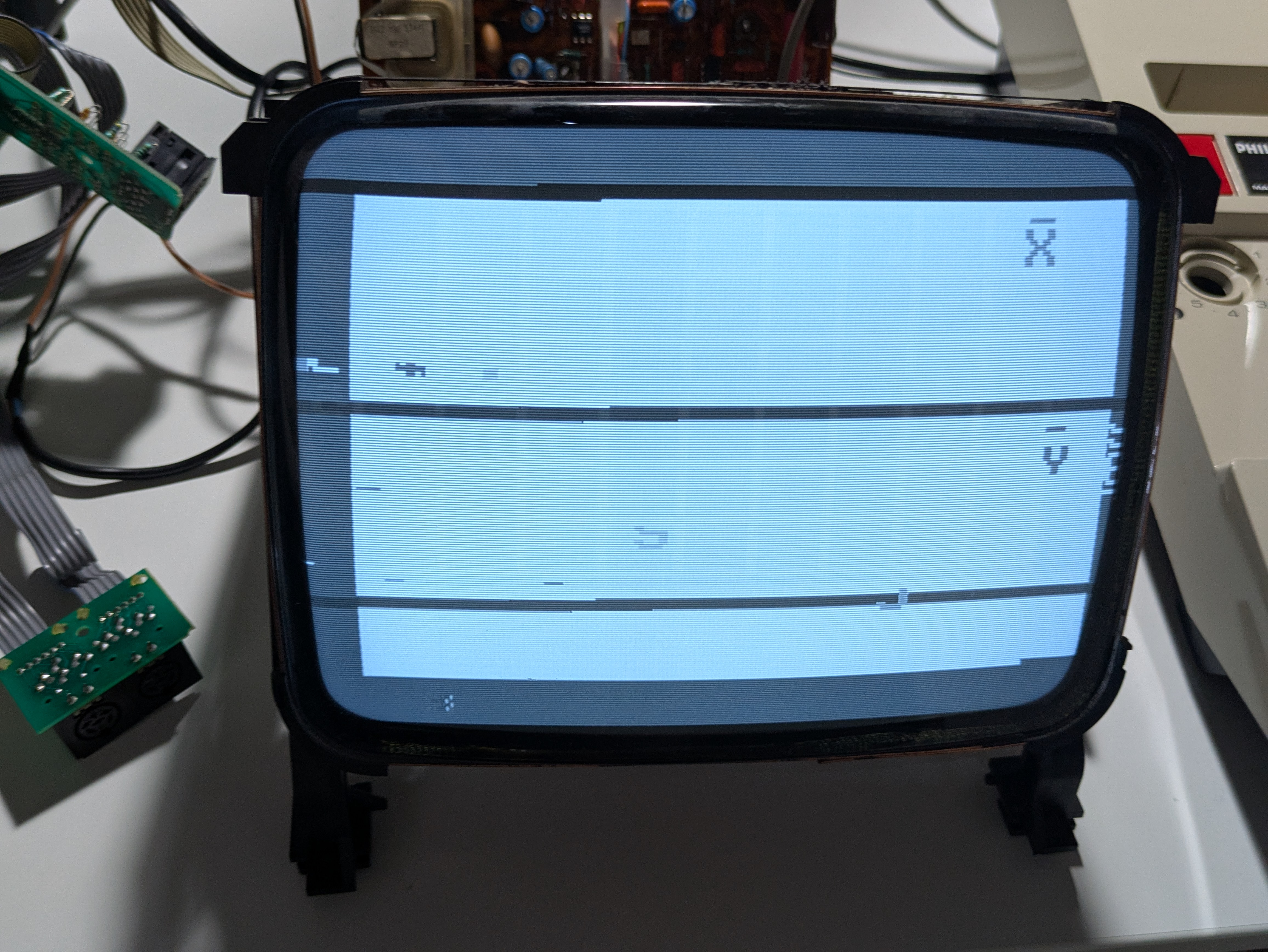
Before / after:
The screen returned to full height:
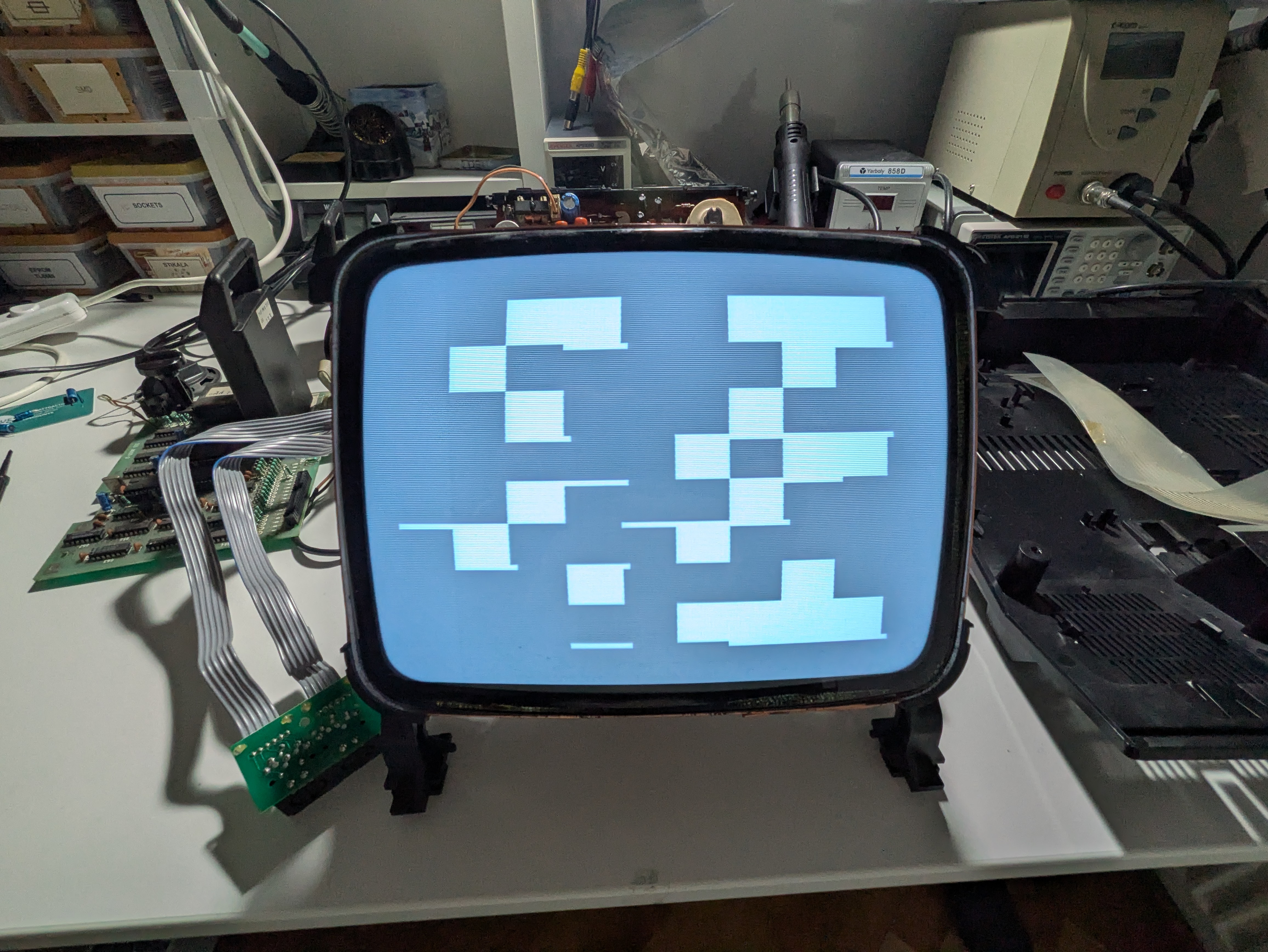
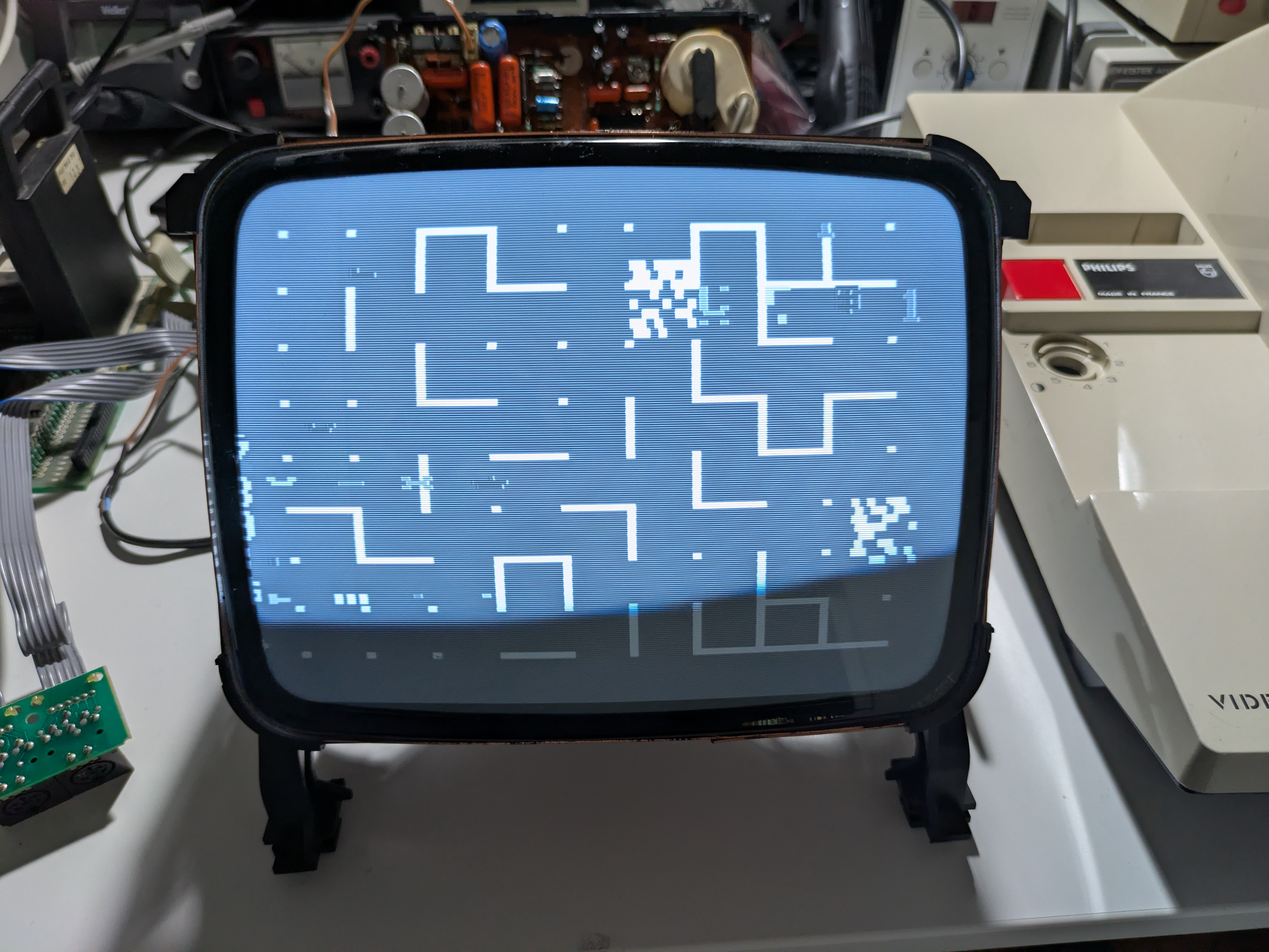
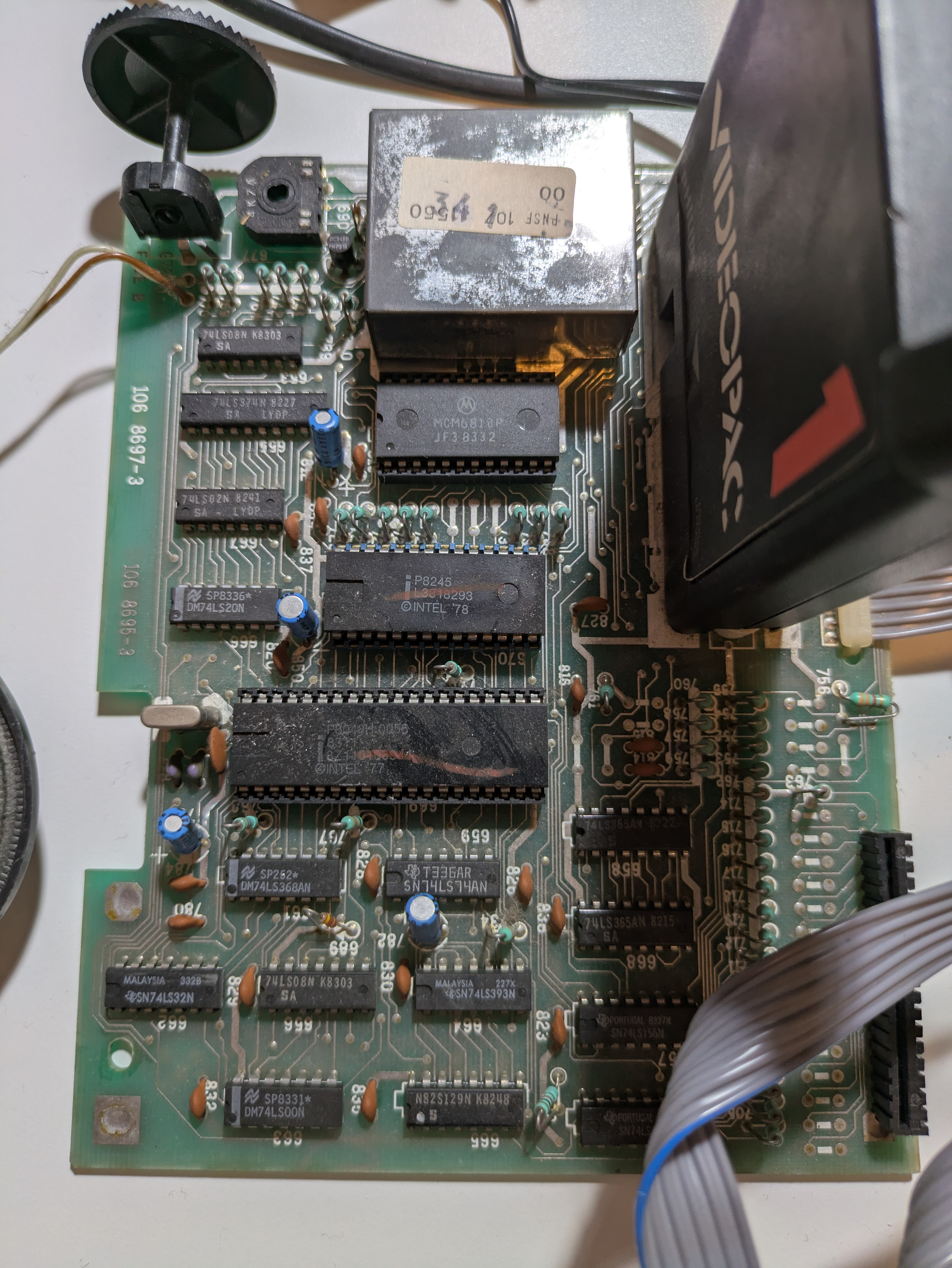
6. A New Symptom Appears: Random Boot Garbage
After fixing the vertical deflection, the console began booting into random image patterns.
I was suspecting instabilities on the power rails. Voltages on the digital board:
- 5V = 5.0 V, OK
- 12V = 12.8V, still OK
- 5V ripple = 230 mVpp
The ripple wasn’t very high so it shouldn’t have been the reason for it. However, I anyway replaced the filtering capacitors C782, C783, C812, and C850:
The ripple persisted and the issue remained.
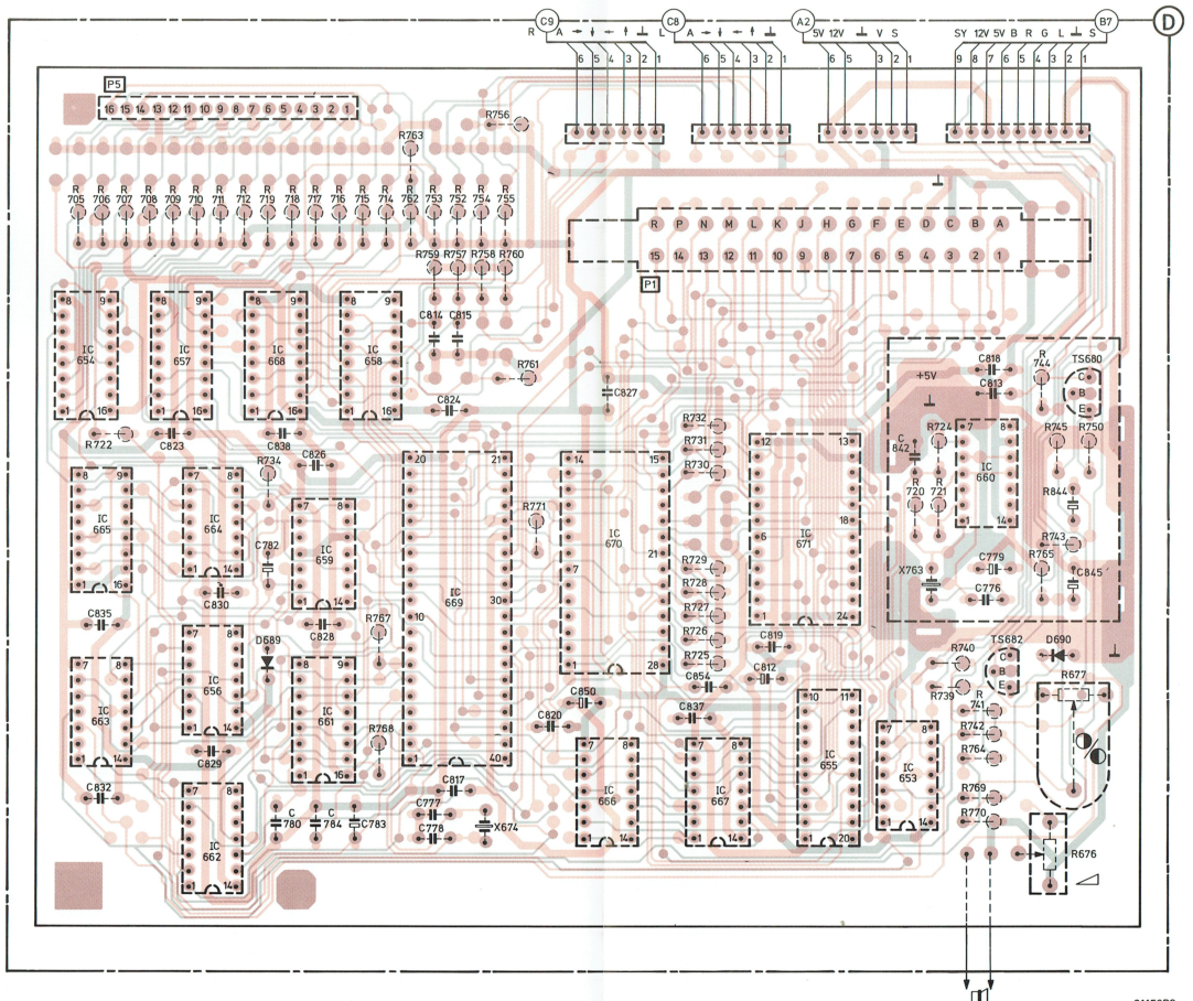
7. The Mystery of the Reset Circuit
I started to suspect that the CPU doesn’t receive a proper reset signal on boot time.
I probed the reset pin of the Intel 8048 CPU (pin 4).
Expected: a reset pulse.
Actual: permanently high.
Tracing the circuit revealed there is no onboard reset circuit.
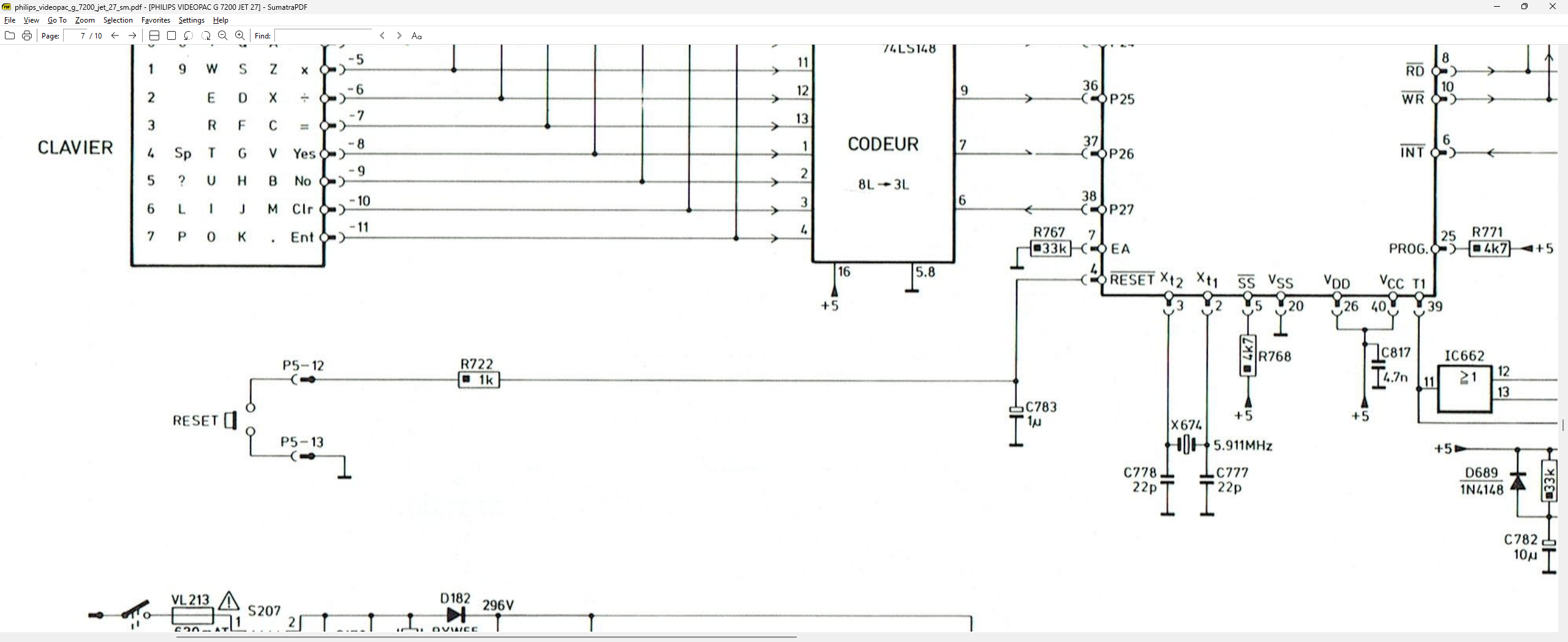
Instead, the reset line is pulled through the keyboard (connector P5 pins 12 and 13).\ Pressing the keyboard reset key sends a brief 5V pulse.
A quirky design, but now understood.
8. Final Assembly and Remaining Work
The CRT now works perfectly, the console boots reliably, and gameplay works as expected.
I also built a DIN6-to-DB9 joystick adapter to use Atari/C64-style joysticks.
Remaining tasks:
- Replace the missing power switch\ (likely this one: https://eu.mouser.com/ProductDetail/Well-Buying/PT-S4PL?qs=v5mWekTF9wqBHgdiG9MjCA%3D%3D)
- Perform video calibration:\ https://wiki.console5.com/tw/index.php?title=Videopac_G7200&mobileaction=toggle_view_desktop
- Find original Philips joysticks to complete the set
9. Conclusion
This repair took me through SMPS debugging, CRT vertical deflection repair, chasing digital noise, and uncovering odd design choices like the keyboard-dependent reset line. The Philips G7200 is a moderately complex machine, but restoring it is incredibly rewarding.
Now it runs beautifully—an unusual hybrid console brought back to life.
If the embedded video does not play, open it directly: clean_machine.mp4